Selecting a Valve Actuator is not a catalog exercise. It is a decision about torque, speed, control accuracy, operating environment, and failure response. A valve that moves only a few times each day has different needs from one modulating flow continuously. Small details matter: a sticky stem, cold outdoor air, or a limited instrument-air supply can change the choice.
The scale of modern infrastructure makes that choice consequential. The International Energy Agency’s Renewables 2023 report recorded nearly 510 gigawatts of renewable power capacity added worldwide in 2023, almost 50% more than in 2022. The UN World Water Development Report 2024 states that agriculture accounts for about 70% of global freshwater withdrawals. These figures do not specify actuator sizes, but they show why dependable flow control matters across energy and water systems. That context helps.
A practical comparison should cover electric, pneumatic, and hydraulic actuators, then test each against the application’s real conditions. Check the valve’s breakaway torque, required stroke time, duty cycle, available power, enclosure rating, and manual override needs. Confirm the mounting interface and control signals, too; standards such as ISO 5211 and IEC 60534 provide useful reference points. Yet published ratings are not the whole story. Actual friction, pressure changes, and maintenance habits can differ from assumptions. No selection is perfect on paper. The aim is a well-supported choice, verified against the valve manufacturer’s data and the site’s operating conditions.

Start with the actual duty, not the actuator catalogue. Record the valve type, size, process medium, pressure differential, temperature, and required flow range. Note how often it cycles and whether it must fail open, fail closed, or hold position during power loss. A valve opening against a high differential pressure may need much more torque than one moving under steady conditions. Include breakaway, running, and seating torque, using the valve maker’s data for the specific service. Small details matter: cold starts, sticky deposits, and long periods between cycles can change what reliable operation looks like.
For control valves, ISA-75.01.01-2012 (IEC 60534-2-1) provides flow-sizing equations; it helps define process conditions, but it does not specify actuator torque. ISO 5211:2017 covers mounting interfaces for part-turn actuators, not the torque your valve needs. Keep those limits clear. A matching flange is not proof of adequate performance. And assumptions can be wrong.
Tips: List minimum and maximum differential pressure, operating temperature, cycle frequency, and available power. Check torque across the full stroke, including seating. If process data are incomplete, flag the uncertainty before selecting an actuator; a tidy calculation can still rest on a poor assumption.
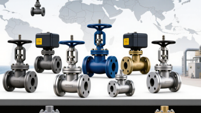
Electric actuators offer precise positioning and straightforward integration with control systems. They suit sites with reliable power and moderate operating speeds. Pneumatic actuators move quickly and tolerate frequent cycling, but they need a dependable compressed-air supply. Air lines also add maintenance points. Hydraulic actuators deliver high torque in compact spaces, making them useful for large or tightly seated valves. Their power units and fluid systems require more space and upkeep. No type wins in every setting.
Match the actuator to the valve’s torque requirement, operating frequency, and available utilities. For example, a large valve that opens only during occasional shutdowns may not need a fast actuator. Check the required fail position, such as whether the valve must close when power or air is lost. Confirm the actuator’s duty rating and environmental protection against actual site conditions. A sizing calculation can help, but real friction and pressure changes may still affect performance. That detail is easy to overlook.
Tips: Compare total installation and maintenance needs, not just purchase cost. Verify the valve stem interface and available mounting space before ordering. If conditions are uncertain, ask a qualified engineer to review the torque margin. A little extra margin helps; excessive oversizing can create its own problems.
Typical relative characteristics of pneumatic, electric, and hydraulic actuators
Ratings are qualitative comparisons, not test results: 1 = lower and 5 = higher. Pneumatic actuators are commonly selected for fast operation, electric actuators for precise positioning, and hydraulic actuators for high force or torque. Actual performance depends on actuator sizing, valve type, controls, and operating conditions.
Choose an actuator from the valve’s required torque or thrust, not its pipe size. Get the valve maker’s tested operating values for the actual pressure, fluid, temperature, and seat material. AWWA Manual M49 discusses how differential pressure and valve type affect operating torque.
ISO 5211:2017 defines mounting interfaces for part-turn actuators; it does not prescribe the torque a valve needs. Keep that distinction clear.
For example, if tested data show a worst-case breakaway torque of 400 N·m, a 1.25 sizing factor gives a minimum actuator output of 500 N·m at the specified supply pressure. This is an illustrative calculation, not a universal safety factor. Check running torque too, and confirm output across the actuator’s full stroke.
For a rising-stem valve, compare required thrust, stem travel, and buckling limits instead. Allow for low air pressure, voltage variation, cold lubricant, and infrequent operation. Small details matter. A clean-water test may not represent a sticky valve after months in service. I still treat the final margin as engineering judgment, not a magic number. Verify the load case with documented valve data and site conditions.
Choosing a valve actuator starts with the power available at the site. Confirm voltage, phase, supply stability, and the actuator’s starting current—not only its running load. The U.S. Department of Energy’s 2014 motor-systems sourcebook reports that motor-driven systems use about 69% of U.S. manufacturing electricity. That figure is not specific to valve actuators, but it shows why efficient sizing matters. Match torque to the valve’s breakaway requirement, and check duty cycle and fail-safe needs. An oversized unit can waste energy; an undersized one may stall when deposits raise operating torque.
Control compatibility is just as important. Verify whether the system requires on-off, modulating, or networked control, then confirm signal type, feedback, and response time. A 4–20 mA command, for example, must match both actuator input and controller configuration. One detail is easy to overlook: the valve may move correctly during commissioning but behave differently under changing process loads. Test realistic operating conditions where possible.
Environmental fit protects performance over time. Check ambient temperature, humidity, vibration, corrosion exposure, and dust or water ingress. IEC 60529 defines IP enclosure ratings; select a rating suited to the actual installation, not just the equipment-room label. Small details matter.
Tips: Before ordering, record supply voltage, control signal, required torque, duty cycle, and enclosure rating. Photograph the nameplate and mounting area. Recheck assumptions with the maintenance team; field conditions are often messier than drawings suggest.
| Selection factor | Electric actuator | Pneumatic actuator | Hydraulic actuator | Manual actuator |
|---|---|---|---|---|
| Power source | AC or DC electrical supply; backup power may be needed if operation must continue during an outage. | Compressed instrument air or gas. Confirm that the supply pressure and available flow meet the actuator requirements. | Pressurized hydraulic fluid from a power unit or hydraulic circuit. | Human input through a lever, handwheel, or gearbox; no external power supply is required. |
| Control and positioning | Suitable for on/off or modulating control when paired with the appropriate controls, feedback, and positioning equipment. | Commonly used for fast on/off operation; modulating control is possible with a suitable positioner and control signal. | Can provide on/off or modulating control when equipped with compatible hydraulic control and feedback components. | Typically suited to local, infrequent operation. Remote or automatic control is not available without additional equipment. |
| Fail-safe operation | May require a spring-return design, battery, or uninterruptible power supply to move the valve to a defined position after power loss. | Spring-return designs can move the valve to a selected fail position when air supply is lost; confirm the required action and available air conditions. | A spring-return design or stored hydraulic energy, such as an accumulator, may provide movement after loss of supply. | Position remains under manual control; automatic movement to a safe position after a process or power failure is not provided. |
| Torque and sizing | Match the actuator's rated output to the valve's required torque or thrust, including the valve manufacturer's safety allowance and worst-case operating conditions. | Verify output at the minimum available air pressure, not just the nominal supply pressure, and account for valve torque throughout the operating stroke. | Check output at the minimum available hydraulic pressure and account for pressure losses, fluid conditions, and the valve's operating requirements. | Confirm that the operator can safely provide the required torque or thrust, including any gearbox ratio and operating frequency. |
| Environmental compatibility | Specify suitable enclosure protection, corrosion resistance, and temperature limits for the installation area. Hazardous locations require appropriately certified equipment. | Consider air quality, moisture, icing risk, exhaust routing, noise, and the actuator's temperature and material limits. | Consider fluid leakage containment, hydraulic-fluid compatibility, cleanliness, temperature, and protection of nearby equipment or the environment. | Check access, operator safety, corrosion resistance, and whether the location permits reliable manual operation. |
| Typical application fit | Useful where electrical power and control integration are available, including applications requiring position feedback or remote commands. | Useful where reliable compressed air is available and rapid operation or a pneumatic fail action is required. | Useful where high force or torque is needed and a hydraulic power source and maintenance capability are available. | Useful for low-frequency operation, isolation valves, or locations where a powered supply is impractical. |
| Key checks before selection | Supply voltage and frequency; duty cycle; required speed; control signal; feedback; enclosure and hazardous-area requirements. | Minimum pressure and air capacity; spring action; operating speed; air quality; exhaust arrangement; positioner requirements. | Operating pressure and flow; fluid type; power-unit availability; leakage controls; required speed and fail-safe arrangement. | Required operating effort; access and clearance; gearbox needs; operating frequency; lockout and position indication. |
Selection note: Actuator output, operating time, temperature limits, and environmental ratings vary by design. Confirm the valve's required torque or thrust and the actuator's certified performance under the actual minimum supply and site conditions.
Choosing a valve actuator starts with the consequences of failure. A fail-open or fail-closed position should match the process hazard, not merely the preferred control signal. Check the valve’s required torque across its full travel, including breakaway torque after long periods without movement. Then verify the actuator’s failure mode, power supply, and response time against the site’s safety plan. OSHA estimates that effective lockout/tagout practices prevent about 120 fatalities and 50,000 injuries each year. That figure concerns hazardous-energy control broadly, but it underscores why isolation and safe access matter during actuator work.
Installation details can change performance. Leave room to remove the actuator cover, reach terminals, and use a torque tool. Confirm that the mounting interface is compatible, the stem is aligned, and wiring or air lines avoid heat, vibration, and standing water. In wet or dusty areas, check the enclosure rating and cable entries. Test the full stroke after installation, and confirm that limit switches and position feedback match the actual valve position. Small misalignments can become recurring faults.
Maintenance needs should influence the choice, too. The U.S. Department of Energy’s Operations & Maintenance Best Practices guide reports that predictive maintenance can cost 8–12% less than preventive maintenance, and 30–40% less than reactive maintenance. Those are broad program estimates, not guaranteed actuator savings. Still, accessible diagnostic points and clear fault indications can make inspections more useful. Keep a record of cycle counts, operating time, and unusual noise. A checklist helps, though it will not catch everything. Review it after real failures.