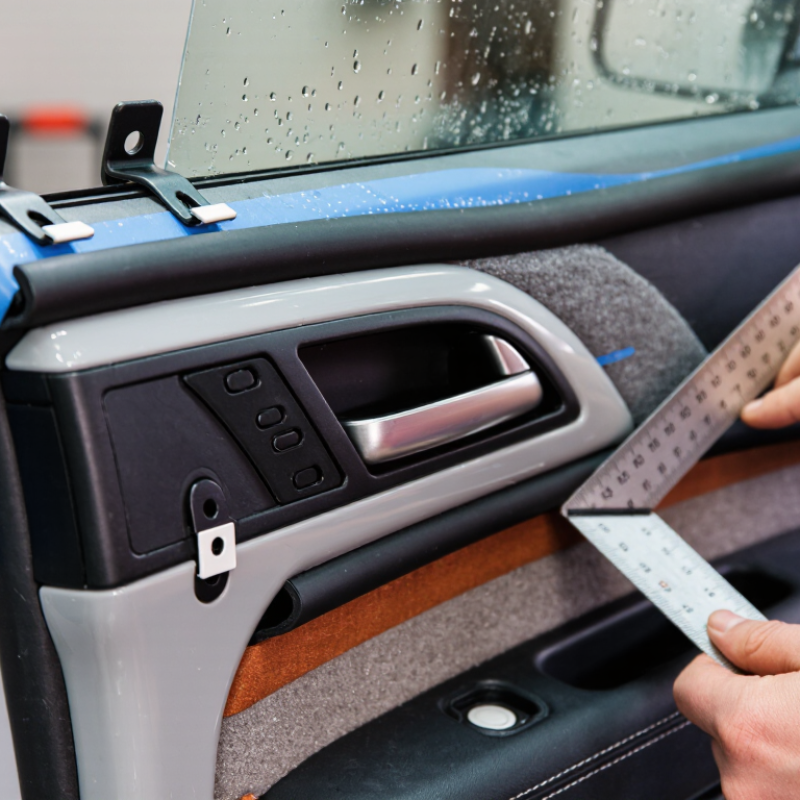
| Vehicle Compatibility | Installation position and vehicle body design | Identify whether the strip is for a door frame, door edge, trunk opening, hood edge, window channel, or fixed glass. | Measure the actual mounting channel or flange rather than selecting by vehicle name alone. | Different body panels use different profiles, clearances, and attachment methods. |
| Existing Seal Profile | Cross-section shape, retaining lip, bulb, or hollow chamber | Remove a short section of the old seal and record its width, height, channel depth, and retaining-lip size. | Common automotive sealing profiles include bulb seals, U-channels, edge trims, and extruded solid strips. | A similar-looking profile may not lock securely or may apply excessive closing force. |
| Mounting Channel Width | Width of the metal or plastic flange receiving the seal | Measure the flange with a vernier caliper at several points; use the largest value plus the required grip allowance specified by the profile. | Typical vehicle flange widths are often approximately 1.0–3.0 mm, but the correct value must be verified on the vehicle. | An undersized channel can slip off, while an oversized retaining section may deform the panel or prevent full seating. |
| Seal Height | Installed height between the body and the closing panel | Measure the gap with the door, hood, or trunk fully closed and compare it with the compressed seal height. | Many bulb-style seals compress by approximately 25%–40% during normal closure. | The seal must compress enough to block water and air without making the panel difficult to close. |
| Installation Length | Total perimeter of the application area | Follow the actual installation path with a flexible tape or cord, then measure the cord. | Required length = measured path length × 1.05–1.10; avoid excessive stretching during installation. | A 5%–10% allowance helps cover trimming, corners, and small measurement errors. |
| Corner Geometry | Sharp bends, radii, and changes in direction | Record the smallest bend radius along the route and select a profile that can follow it without kinking. | Use gradual bends where possible; do not force a rigid or reinforced seal around a tight corner. | Kinks and wrinkles create leakage paths and can cause the seal to pull away from the channel. |
| Material | Resistance to weather, water, heat, ozone, and automotive fluids | Choose a material according to the exposure level and installation location. | EPDM: strong resistance to water, ozone, and weathering.
Silicone: broad temperature capability and good flexibility.
PVC: commonly used for trim and edge protection; verify heat and weather requirements. | Material compatibility affects service life, flexibility, and resistance to cracking or hardening. |
| Temperature Range | Expected ambient and under-hood temperature | Check the supplier’s temperature rating against the installation location. | Door and trunk seals commonly require approximately −40°C to +80°C or higher; under-hood areas may require higher-temperature materials. | A seal that is not rated for the environment may become brittle, soft, or permanently deformed. |
| Hardness and Flexibility | Compression resistance and ability to follow body contours | Compare the product’s Shore A hardness and manually check flexibility at the intended bend radius. | Many flexible automotive rubber seals fall roughly within 60–80 Shore A, depending on profile and application. | Too hard can increase closing force; too soft may collapse and lose sealing pressure. |
| Attachment Method | Push-fit, adhesive-backed, clip-on, or bonded installation | Match the attachment method to the substrate and the original seal design. | Push-fit for retaining flanges
Adhesive-backed for clean, flat surfaces
Bonded for fixed glass or specialized applications | The wrong attachment method can lead to peeling, movement, rattling, or water intrusion. |
| Adhesive Surface Preparation | Cleanliness, temperature, and surface condition | Remove dirt, wax, oil, loose paint, and old adhesive; allow the surface to dry completely. | For most pressure-sensitive adhesives, installation is more reliable on a clean surface above approximately 15°C. | Contamination and low temperatures reduce initial tack and long-term adhesion. |
| Water Drainage | Factory drain holes and water-flow paths | Do not cover, seal, or redirect original drain openings in doors, rocker panels, or trunk channels. | Inspect drain holes before and after installation, especially along the lower edge of doors. | Blocked drainage can trap water and contribute to corrosion or interior leaks. |
| Closing Force Check | Door, hood, or trunk operation after installation | Close the panel slowly and confirm even contact without panel rebound, excessive resistance, or latch misalignment. | The panel should close using normal operating force and the seal should show continuous, even compression. | Excessive compression can distort the panel, stress the latch, or shorten seal life. |
| Measurement Example | Door-frame perimeter | Measured path: 3,420 mm; allowance: 8% | Required length = 3,420 × 1.08 = 3,693.6 mm, so select at least 3.70 m before final trimming. | Using a calculated allowance reduces the risk of a short joint or overstretched seal. |
| Final Fit Test | Water, wind-noise, and visible-contact inspection | Inspect the entire perimeter, perform a gentle water test, and check for gaps or areas with no contact. | Contact should be continuous around corners and along straight sections without visible gaps or bulges. | A final inspection confirms that the selected size and installation method provide a complete seal. |