Global buyers entering 2026 face a wider Automatic Valve market, but more complicated purchasing decisions. Valve selection now affects energy use, uptime, safety, and maintenance costs. MarketsandMarkets’ Industrial Valves Market research indicates continued mid-single-digit growth through 2028, driven by water treatment, energy, chemicals, and manufacturing. Grand View Research also identifies industrial automation and process optimization as important demand factors.
No valve wins everywhere. A compact stainless-steel ball valve may isolate clean water quickly, while a butterfly valve can reduce weight and installation space in large pipelines. Globe and control valves offer finer flow regulation, especially in steam, chemical, and temperature-sensitive systems. Gate valves suit full-open or full-closed service, but they may respond too slowly for frequent throttling. Diaphragm valves can protect hygienic or corrosive processes, although diaphragm life requires careful review.
This guide compares the best Automatic Valve types for global buyers in 2026. It considers pressure class, media compatibility, temperature range, actuation speed, fail-safe behavior, and expected cycle frequency. ISO 5211 mounting compatibility can simplify actuator replacement. IEC 60534 remains relevant for control valve sizing and performance evaluation. Buyers should also examine IP ratings, SIL requirements, regional certifications, spare-part availability, and local service capability.
Small details matter. A dusty outdoor plant may need stronger enclosure protection than a clean indoor line. A remote water station may favor electric actuation, while a fast emergency shutdown often needs pneumatic power. Reported market forecasts vary because researchers define “industrial valve” differently. That limitation deserves attention. The right choice is not the most expensive valve, but the one matched to the process, risk profile, and maintenance reality.
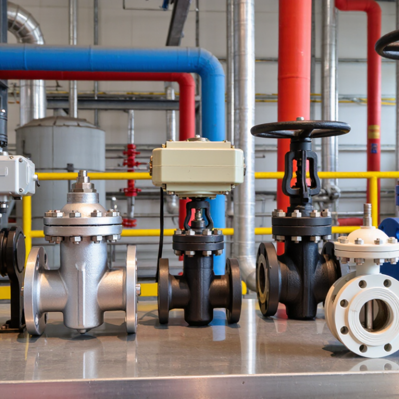
Automatic valves control fluid flow without continuous hand operation. A controller sends an electrical, pneumatic, or hydraulic signal to an actuator. The actuator then rotates or moves the valve stem. Ball and butterfly valves usually turn through 90 degrees. Globe valves move linearly for more precise throttling.
The control loop may include a sensor, positioner, and feedback signal. When pressure or temperature changes, the controller adjusts valve position. Spring-return actuators can close or open during power loss. This detail matters in steam, water treatment, and process lines. It is not always simple. Incorrect sizing can cause noise, unstable control, or premature seat damage.
The U.S. Department of Energy reports that compressed-air systems can consume about 10% of industrial electricity. Its compressed-air guidance also notes that leaks commonly waste 20–30% of compressor output. Automatic isolation valves can reduce this loss when paired with leak monitoring and suitable pressure settings. Buyers should check flow coefficient, pressure class, temperature range, actuator torque, enclosure rating, and media compatibility. ISO 5211 provides widely used mounting dimensions for quarter-turn actuators, while IEC 60534 supports control-valve sizing practices. These standards improve interchangeability, but they do not replace site testing. A valve that performs well in a clean-water trial may behave differently with abrasive slurry, cold gas, or contaminated air.
| Automatic Valve Type | How It Operates | Typical Actuation or Control Input | Common Fail-Safe Behavior | Typical Response Speed | Common Size Range | Typical Fluid and Pressure Considerations | Best-Fit Applications | Key Buying Considerations for Global Projects |
|---|---|---|---|---|---|---|---|---|
| Direct-Acting Solenoid Valve | An electromagnetic coil moves a plunger directly to open or close a small flow passage. The valve changes state when the coil is energized or de-energized. | 24 V DC 110 V AC 230 V AC On/off electrical signal | Normally closed, normally open, or universal designs are available. The actual fail position depends on the selected configuration. | Approximately 10–100 milliseconds for many small models | Typically DN2–DN25 for direct-acting designs | Suitable for clean air, water, gases, oils, and other compatible media. Pressure capability is highly dependent on orifice size, coil power, seal material, and fluid type. | Compact equipment, water treatment skids, dispensing systems, pneumatic pilot circuits, and laboratory equipment | Confirm voltage and frequency, coil enclosure rating, duty cycle, seal compatibility, minimum operating pressure, and local electrical certification requirements. |
| Pilot-Operated Solenoid Valve | A solenoid opens a pilot passage, allowing line pressure to move the main diaphragm or piston. It normally requires a pressure differential to operate. | 24 V DC 110 V AC 230 V AC On/off electrical signal | Normally closed or normally open configurations are common. The spring determines the position when the coil is de-energized. | Approximately 20–500 milliseconds, depending on size and pressure conditions | Typically DN15–DN100, with larger designs available | Efficient for larger flow passages, but many designs require a minimum differential pressure. Media cleanliness and diaphragm compatibility are important. | Water distribution, compressed air, irrigation, industrial utility lines, and general process control | Check minimum differential pressure, maximum pressure, flow coefficient, coil power consumption, ingress protection, and approvals for the destination market. |
| Electric Quarter-Turn Valve | An electric actuator rotates a ball, butterfly, or plug valve through approximately 90 degrees between open and closed positions. | On/Off 24 V DC 100–240 V AC Optional 4–20 mA or proportional control | Fail-in-place is common. Battery-backed, spring-return, or supercapacitor options can provide fail-open or fail-closed action. | Approximately 5–60 seconds for a 90-degree stroke | Typically DN15–DN600, depending on valve design and torque requirement | Suitable for water, air, gases, and many process fluids. Valve torque increases with pressure, temperature, solids, and seat friction. | HVAC, water treatment, building automation, process isolation, and utility pipelines | Verify actuator torque margin, manual override, duty rating, enclosure protection, limit switches, travel feedback, and regional power compatibility. |
| Electric Linear Control Valve | An electric actuator moves a stem and plug or other throttling element in a linear direction to regulate flow rather than simply switching it on or off. | 4–20 mA 0–10 V Fieldbus Programmable position control | Fail-in-place is typical unless a spring-return or emergency power module is included. | Approximately 10–120 seconds for a full stroke | Typically DN15–DN300, depending on pressure class and flow requirement | Provides accurate flow, pressure, or temperature control. Cavitation, flashing, noise, and excessive differential pressure must be evaluated during sizing. | Steam, hot-water systems, chilled-water systems, process control loops, and energy management systems | Match the actuator signal, stroke time, shutoff force, control accuracy, valve characteristic, leakage class, and communication protocol with the control system. |
| Pneumatic Quarter-Turn Valve | Compressed air acts on a piston or diaphragm actuator to rotate a ball, butterfly, or plug valve. A solenoid pilot valve usually controls the air supply. | 3–8 bar air Commonly controlled by a 3/2 or 5/2 solenoid valve | Spring-return actuators can be fail-open or fail-closed. Double-acting actuators generally fail in place if air pressure is lost unless an additional safety system is installed. | Approximately 0.1–10 seconds for a 90-degree stroke | Typically DN15–DN600, depending on actuator torque and valve type | Well suited to hazardous or wet areas when correctly configured. Instrument air should be clean, dry, and regulated; actuator sizing must account for breakaway torque. | Chemical processing, oil and gas facilities, water treatment, bulk handling, and emergency shutdown systems | Confirm air quality, available pressure, spring-failure direction, required safety position, area classification, cycle frequency, and actuator corrosion protection. |
| Pneumatic Linear Control Valve | A pneumatic diaphragm or piston actuator moves a stem and plug continuously to regulate flow. A positioner converts the control signal into accurate stem movement. | 3–15 psi 4–20 mA Electro-pneumatic positioner | Spring-return designs can be configured for fail-open, fail-closed, or fail-in-place behavior depending on the actuator and accessories. | Approximately 1–30 seconds for a full stroke | Typically DN15–DN300, with larger sizes available for specialized services | Suitable for throttling steam, gases, liquids, and process fluids. Proper sizing is required to avoid instability, cavitation, flashing, and excessive noise. | Refineries, power generation, chemical plants, steam control, and continuous process industries | Evaluate flow characteristic, valve travel, leakage class, noise level, positioner compatibility, instrument-air demand, and maintenance access. |
| Hydraulic Actuated Valve | Pressurized hydraulic fluid drives a piston or cylinder to move the valve. Hydraulic power provides high force and is often used for large or high-pressure valves. | Hydraulic pilot pressure Electrical solenoid pilot or hydraulic control system | Can be designed to fail-open, fail-closed, or lock in the last position using accumulators, springs, or hydraulic control circuits. | Approximately 0.5–30 seconds, depending on cylinder size and hydraulic circuit | Typically DN50–DN2000 for large industrial and infrastructure applications | Provides high operating force for large valves and high differential pressures. Hydraulic-fluid leakage, temperature, filtration, and fire resistance require attention. | Hydropower, large water pipelines, emergency shutdown systems, marine systems, and heavy industrial equipment | Check hydraulic pressure availability, accumulator capacity, fluid compatibility, leakage control, emergency stroke time, and local safety requirements. |
| Self-Operated Pressure-Regulating Valve | Downstream or upstream pressure acts through a diaphragm, piston, or pilot system against a spring to regulate pressure without an external power source. | Process pressure and spring setting; optional remote pilot or monitoring device | There is no electrical fail position. The final behavior depends on the valve design, spring arrangement, upstream pressure, and downstream conditions. | Typically fractions of a second to several seconds, depending on design and system dynamics | Typically DN15–DN600, depending on service and pressure class | Designed for pressure reduction, pressure sustaining, back-pressure control, or differential-pressure regulation. Stable inlet pressure, flow range, and impulse-line installation are important. | Water networks, gas distribution, steam systems, irrigation, and utility pressure management | Confirm set-pressure range, minimum and maximum flow, pressure ratio, droop, cavitation risk, sensing-line arrangement, and adjustment access. |
| Thermostatic Automatic Valve | A temperature-sensitive element expands or contracts to move a valve plug, regulating flow according to the sensed temperature without requiring external electrical power. | Temperature setpoint controlled by a wax, bellows, or fluid-filled sensing element | Usually spring-return toward a defined position, but the exact behavior depends on whether the valve controls heating or cooling flow. | Typically several seconds to several minutes, depending on sensor design and temperature change | Typically DN10–DN100 for common heating and cooling applications | Often used with water, hot water, steam, or thermal fluids. Maximum temperature, response time, sensor location, and pressure drop must be checked. | Radiators, heat exchangers, cooling circuits, domestic hot-water systems, and thermal protection systems | Specify temperature range, sensing method, connection type, maximum differential pressure, fluid compatibility, and required control accuracy. |
| Motorized Mixing or Diverting Valve | An electric actuator positions a rotary or linear valve element to mix two streams or direct one stream between different outlets. | 3-point floating 0–10 V 4–20 mA Modulating controller | Fail-in-place is common. Spring-return options can move the valve to a defined safe position during power loss. | Approximately 30–180 seconds for a complete travel cycle | Typically DN15–DN200 for HVAC and process applications | Correct port orientation, flow direction, authority, and pressure drop are essential. The valve must be sized for stable mixing or diverting performance. | Heating and cooling systems, district energy, heat pumps, boiler circuits, and process temperature control | Check port configuration, actuator control mode, rotation direction, valve authority, close-off pressure, manual override, and controller compatibility. |